Board-to-board connectors play a crucial role in modern electronics, enabling efficient communication between multiple printed circuit boards (PCBs) within a single device. As electronic devices become increasingly compact and complex, the choice of appropriate connectors becomes paramount for ensuring optimal performance, reliability, and manufacturability. Understanding the various types of board-to-board connectors and their applications is essential for PCB designers and engineers to create effective and innovative electronic products.
Common board-to-board connector types used in pcbs
The world of board-to-board connectors is diverse, with various types designed to meet specific requirements in PCB design. Each connector type offers unique features and benefits, making them suitable for different applications. Let’s explore some of the most common board-to-board connector types used in PCBs today.
Pin header connectors for simple board connections
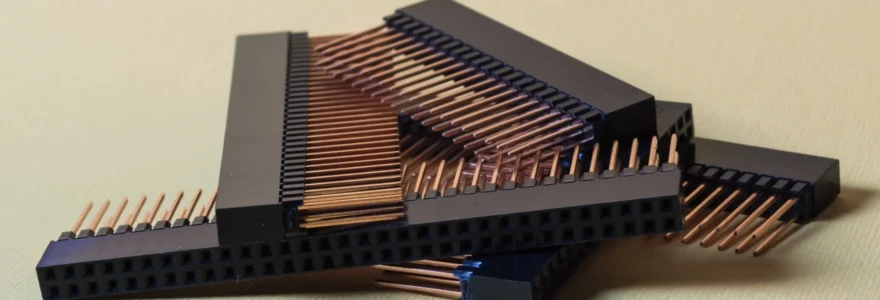
Pin header connectors are among the most basic and widely used board-to-board connectors in PCB design. These connectors consist of a series of metal pins arranged in one or more rows, typically with a standard pitch of 2.54mm (0.1 inches). Pin headers are versatile and can be used for both permanent and temporary connections between boards.
One of the key advantages of pin header connectors is their simplicity and cost-effectiveness. They are easy to install and can be soldered directly onto the PCB or used with mating sockets for removable connections. Pin headers are commonly used in prototype designs, development boards, and applications where frequent board swapping or modifications are necessary.
High-speed mezzanine connectors for stacking boards
As electronic devices become more compact and data rates increase, high-speed mezzanine connectors have gained popularity for stacking PCBs in a parallel configuration. These connectors are designed to support high-frequency signals and provide excellent signal integrity, making them ideal for applications such as telecommunications equipment, servers, and high-performance computing systems.
FFC/FPC connectors offering flexibility between boards
Flexible Flat Cable (FFC) and Flexible Printed Circuit (FPC) connectors provide a unique solution for connecting boards in tight spaces or applications requiring flexible connections. These connectors use thin, flat cables or flexible PCBs to transmit signals between boards, offering excellent space-saving capabilities and design flexibility.
Factors to consider when choosing board-to-board connectors
Selecting the right board-to-board connector for a PCB design involves careful consideration of various factors. The choice of connector can significantly impact the overall performance, reliability, and manufacturability of the final product. Here are some key factors to consider when choosing board-to-board connectors:
1. Electrical Requirements: Consider the voltage, current, and signal frequency requirements of your application. High-speed designs may require specialized connectors with controlled impedance and minimal crosstalk.
2. Mechanical Considerations: Evaluate the physical constraints of your design, including board-to-board spacing, connector height, and mating force. Ensure that the chosen connector can withstand any expected mechanical stress or vibration.
3. Environmental Factors: Consider the operating environment of your device. Some applications may require connectors with enhanced protection against moisture, dust, or extreme temperatures.
4. Reliability and Durability: Assess the expected lifespan of your product and choose connectors with appropriate mating cycles and long-term reliability characteristics.
5. Cost and Availability: Balance the performance requirements with cost considerations and ensure that the selected connectors are readily available from multiple sources to avoid supply chain issues.
By carefully evaluating these factors and consulting with connector manufacturers or suppliers, designers can make informed decisions when selecting board-to-board connectors for their PCB designs. It’s often helpful to refer to a comprehensive connector guide to understand the various options available and their specific characteristics.
PCB layout techniques for optimal connector placement
Proper placement and routing of board-to-board connectors are crucial for achieving optimal performance and reliability in PCB designs. Careful consideration of connector placement can help minimize signal integrity issues, reduce EMI, and improve overall system performance. Let’s explore some key PCB layout techniques for optimal connector placement.
Connector orientation impacts signal integrity performance
The orientation of board-to-board connectors can significantly impact signal integrity performance, especially in high-speed designs. When placing connectors, consider the following guidelines:
1. Align connectors to minimize the length of high-speed traces.
2. Orient connectors to facilitate proper grounding and shielding.
3. Consider the impact of connector orientation on overall board stack-up and layer transitions.
4. Evaluate the potential for crosstalk between adjacent connector pins and nearby traces.
5. Ensure that the chosen orientation allows for proper heat dissipation and thermal management.
Proper connector footprint spacing prevents issues
Accurate connector footprint spacing is essential for ensuring proper mating and preventing mechanical stress on the PCB. When designing connector footprints, keep the following points in mind:
1. Follow manufacturer guidelines for pad sizes and spacing.
2. Allow sufficient clearance around connectors for assembly and rework.
3. Consider the impact of manufacturing tolerances on connector placement.
4. Ensure that nearby components do not interfere with connector mating or unmating.
5. Implement proper fiducial marks for accurate placement during assembly.
By paying close attention to connector footprint spacing, designers can avoid issues such as misalignment, incomplete mating, or mechanical stress that could lead to connector failure or reliability problems.
Routing differential pairs to connectors correctly
For high-speed designs using differential signaling, proper routing of differential pairs to board-to-board connectors is critical for maintaining signal integrity. Consider the following techniques when routing differential pairs:
1. Maintain consistent trace length and spacing within each differential pair.
2. Use symmetric routing techniques to minimize skew between differential pairs.
3. Avoid layer transitions for differential pairs whenever possible.
4. Implement proper termination techniques near connector pins.
5. Use ground planes and guard traces to isolate differential pairs from other signals.
Proper routing of differential pairs is essential for maintaining signal integrity and minimizing EMI in high-speed board-to-board connections.
By implementing these PCB layout techniques, designers can optimize connector placement and routing, leading to improved signal integrity, reduced EMI, and enhanced overall system performance.
Testing procedures to validate board-to-board connections
Thorough testing of board-to-board connections is essential to ensure the reliability and performance of the final product. Implementing comprehensive testing procedures can help identify potential issues early in the development process, reducing the risk of field failures and costly rework. Here are some key testing procedures to validate board-to-board connections:
1. Continuity Testing: Perform basic continuity tests to verify that all intended connections are properly made and that there are no short circuits between adjacent pins.
2. Impedance Testing: For high-speed connections, use time-domain reflectometry (TDR) or vector network analysis (VNA) to measure and validate the impedance of critical signal paths.
3. Signal Integrity Testing: Conduct eye diagram measurements and bit error rate (BER) testing to assess the quality of high-speed signals passing through the board-to-board connectors.
4. EMI/EMC Testing: Perform electromagnetic interference (EMI) and electromagnetic compatibility (EMC) testing to ensure that the board-to-board connections do not introduce unacceptable levels of electromagnetic radiation or susceptibility.
5. Environmental Testing: Subject the assembled boards to relevant environmental tests, such as temperature cycling, vibration, and humidity, to verify the reliability of the connections under expected operating conditions.
Implementing these testing procedures can help designers identify and address potential issues with board-to-board connections before they become problematic in the final product. It’s important to develop a comprehensive test plan that covers all critical aspects of the design and aligns with industry standards and best practices.
Industry standards applicable to board-to-board connectors
Adherence to industry standards is crucial when designing and implementing board-to-board connectors in PCB designs. These standards ensure interoperability, reliability, and consistency across different manufacturers and applications. Let’s explore some of the key industry standards applicable to board-to-board connectors.
IPC standards cover connectors extensively
The Institute for Printed Circuits (IPC) provides several standards that are directly applicable to board-to-board connectors and their implementation in PCB designs. Some of the most relevant IPC standards include:
1. IPC-A-610: Acceptability of Electronic Assemblies
2. IPC-7351: Generic Requirements for Surface Mount Design and Land Pattern Standard
3. IPC-2221: Generic Standard on Printed Board Design
4. IPC-4101: Specification for Base Materials for Rigid and Multilayer Printed Boards
These standards provide guidelines for connector design, PCB layout, assembly processes, and quality control. Designers should familiarize themselves with these standards to ensure compliance and best practices in their board-to-board connector implementations.
Specific connector manufacturer standards may apply
In addition to industry-wide standards, many connector manufacturers develop their own proprietary standards and guidelines for their products. These manufacturer-specific standards often provide detailed information on:
- Connector design and performance specifications
- Recommended PCB layout and footprint designs
- Assembly and handling procedures
- Testing and validation methodologies
- Application-specific usage guidelines
When working with board-to-board connectors from a specific manufacturer, it’s essential to consult their documentation and adhere to their recommended practices to ensure optimal performance and reliability.
System-level industry standards impact connector choice
The choice of board-to-board connectors can also be influenced by system-level industry standards specific to certain applications or market segments. For example:
1. Automotive: Standards such as USCAR-2 and ISO 26262 may impact connector selection for automotive electronics.
2. Aerospace: Standards like DO-160 and MIL-STD-810 can influence connector choices for avionics and military applications.
3. Telecom: Standards such as PICMG and ATCA may dictate specific connector requirements for telecommunications equipment.
4. Consumer Electronics: Standards like USB, HDMI, and PCIe can impact board-to-board connector selection in consumer devices.
5. Industrial: Standards such as IEC 61131 and ISO 13849 may influence connector choices for industrial control systems.
By considering these various standards and guidelines, PCB designers can make informed decisions when selecting and implementing board-to-board connectors, ensuring that their designs meet industry requirements and best practices.